Table of Contents
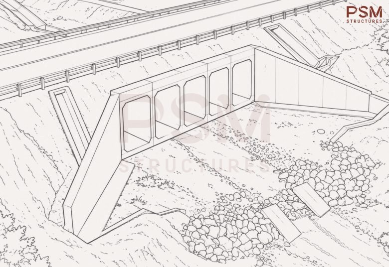
A box culvert looks like the simplest structure on a project. It is a concrete box that carries a road or an embankment over a small watercourse or service crossing. Yet that plain appearance hides a structure where every part carries a different load, in a different direction, often at the worst possible moment.
Understanding what each part does, and what it has to withstand, is the difference between a culvert that sits quietly under traffic for decades and one that cracks, settles, or scours out. This guide walks through the parts of a box culvert and the job each one has to do, for the people who specify, tender, or build them.
What Is a Box Culvert?
A box culvert is a rigid, closed reinforced concrete frame, usually square or rectangular in section, built either as a single cell or as several cells side by side. It carries the load above it, an embankment, a road, and the traffic on it, across an opening while allowing water or services to pass through. For a fuller primer, see what a precast concrete box culvert is. In Indian practice, culverts of this kind fall under IRC:SP:13, the guidelines for the design of small bridges and culverts, with the loads and the concrete design drawn from the wider bridge codes.
One idea decides everything that follows: a box culvert behaves as one continuous frame, not as separate slabs and walls resting on each other. Load applied to any face travels through the whole frame, which is exactly why each part has to be understood in relation to the others.
The Parts of a Box Culvert and What Each One Carries
The box is made up of a small number of parts, and each one has a distinct structural job. Taken together they form the closed frame; taken separately, each is sized for a different load.
The Top Slab
The top slab is the roof of the box and the part that takes the most direct punishment. It carries its own weight, the weight of any earth cushion and wearing surface above it, and the live load from traffic. That traffic load follows the standard vehicle loading in IRC:6, where designers adopt IRC Class A, Class AA, or Class 70R depending on the road's class and importance, with an impact allowance for moving wheels. Where a cushion of fill sits above the culvert, the wheel load disperses as it travels down, commonly assumed at 45 degrees, so it reaches the slab as a wider, gentler patch. Where the road sits almost directly on the slab, the same wheel arrives far more concentrated, which is why a culvert with little or no cushion is often the more demanding case.
The Bottom Slab (Raft)
The bottom slab, or raft, is the floor of the box and the part most people forget. It does not simply sit on the ground. It resists the upward reaction of the soil pushing back against everything above it, and it distributes the whole load of the culvert and its traffic onto the founding soil at a pressure the ground can safely carry. In soft or variable soils, the raft is what keeps the structure from settling unevenly.
The Side Walls
The side walls are the vertical members, and they lead a double life. They act as props between the top and bottom slabs, and they act as retaining walls holding back the earth on either side. They resist lateral earth pressure, water pressure when the surrounding ground is saturated, and the surcharge from traffic near the culvert, treated as an equivalent height of earth. In a multi-cell box culvert, the intermediate walls also carry a share of the vertical load down to the raft.
The Haunches
The haunches are the chamfered fillets at the inside corners where the slabs meet the walls. They are small and easy to dismiss, but the corners of a rigid frame attract the highest bending moments, and the haunches thicken the section exactly there, reducing stress concentration, improving the moment capacity at the joint, and helping water flow through the barrel.
The Wing Walls
The wing walls flare out from the ends of the barrel to retain the embankment where the road meets the opening. They hold back the sloping fill at the inlet and outlet, guide the water into and out of the culvert, and protect the earthwork from being washed away at the transition.
The Cut-off Walls and Aprons
The cut-off walls and aprons sit at the inlet and outlet, below and around the opening. Their job is to stop water from scouring the soil out from under the foundation. Scour is one of the most common reasons culverts fail over time, and these parts exist purely to prevent the ground beneath the structure from being undermined.
The Wearing Coat and Earth Cushion
The wearing coat and cushion are the surface and fill above the top slab. The wearing coat protects the deck and spreads the load; the earth cushion disperses concentrated wheel loads over a wider area before they reach the slab. How much cushion there is changes the load path, which is why the MoRTH standard plans for box culverts come in with-cushion and without-cushion versions.
| Part | What it must withstand |
|---|---|
| Top slab | Dead load, earth cushion, and dispersed live load (IRC:6 Class A / AA / 70R) |
| Bottom slab (raft) | Upward soil reaction; distributes total load to the founding strata |
| Side walls | Lateral earth pressure, water pressure, and live-load surcharge |
| Intermediate walls | A share of the vertical load in multi-cell culverts |
| Haunches | The peak bending moments at the frame corners |
| Wing walls | The embankment fill at the inlet and outlet |
| Cut-off walls | Scour that would undermine the foundation |
How the Parts Work Together as a Rigid Frame
Each part matters, but the culvert only makes sense as a whole. Because the slabs and walls are cast (or connected) into a continuous frame, load on the top slab induces moments in the walls, and earth pressure on the walls induces moments in the slabs. The corners, stiffened by the haunches, are where these effects concentrate.
Decision factor: A box culvert is only as good as its corners. That is where the frame's bending moments peak, and where detailing, not concrete, decides whether it lasts.
The Load Cases That Govern a Box Culvert Design
The worst case is rarely the obvious one, so designers check the frame under several load cases:
- The culvert empty but carrying live load on top.
- The culvert running full of water with no traffic above.
- The culvert full with live load.
Each is considered with and without the earth cushion. A shallow cushion tends to produce higher negative moments at the slab-to-wall junctions, while deeper fill increases the lateral earth pressure on the walls. The reinforced concrete design follows the limit-state provisions of IRC:112 and IS 456, and standard configurations for single, double, and triple cell culverts are set out in the MoRTH standard drawings.
Specifying or tendering a box culvert?
PSM Structures designs and details precast culverts to the relevant IRC, IS and MoRTH requirements, so every part is sized for the job it actually has to do.
Discuss Your Project →How Precast Changes the Way the Parts Come Together
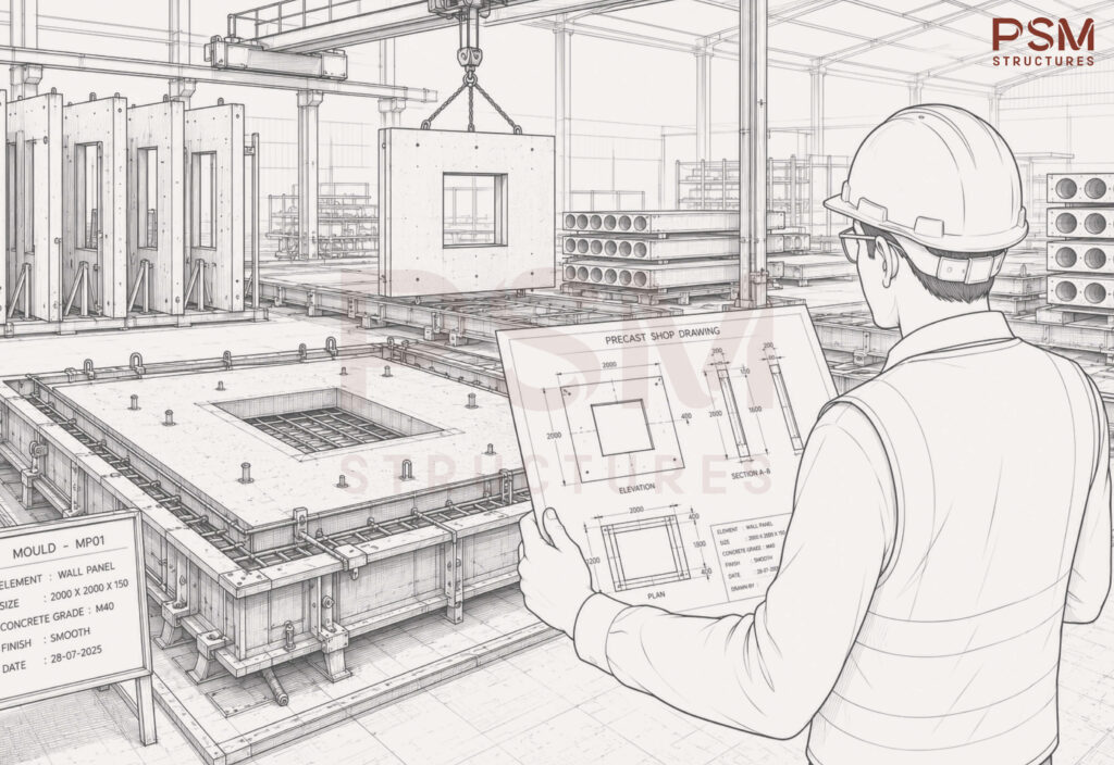
The parts of a box culvert do not change when you precast it, but the quality with which they come together does. Casting the frame in a controlled yard means the geometry, the cover to reinforcement, and the concrete quality are far more consistent than they can be in a trench beside a live road. That consistency is exactly what the corners and the cover need to perform as designed.
Precasting also compresses the program, because the units are produced while site works continue and installed in a fraction of the time of a cast-in-situ pour. We have written more broadly on where precast concrete earns its place. For a culvert, the gain is that the parts arrive already made to the tolerances the design assumed.
Where Box Culvert Design and Detailing Make the Difference
Most culvert problems are not concrete problems. They are detailing problems: reinforcement congested at the haunches, cover that is not maintained, a wing wall sized for the wrong slope, or a cut-off wall too shallow for the expected scour. Every one of those traces back to how carefully the parts were designed and detailed for the specific site, loads, and soil, rather than lifted unchanged from a standard drawing.
Decision factor: Standard drawings are a starting point, not an answer. They assume a span, a cushion depth, a soil and a loading; used unchanged where those differ, they hide the weakness until the culvert is in service.
The work a specialist team does is take the loads from IRC:6, the design rules from IRC:112 and IS 456, the culvert guidelines of IRC:SP:13, and the realities of the ground, and turn them into a culvert where every part is sized correctly.
A box culvert tempts everyone to treat it as a commodity, because it looks like one. The parts that decide its life, the corners, the cut-off walls, the cover, are exactly the ones a commodity approach skips. Design the loads and the detailing for the real site, and a plain concrete box carries a highway for decades.
Parv Modh
Want box-culvert detailing that holds up on site?
Tell us the crossing, the span, and the soil, and we will design and detail the culvert to the actual conditions, not just a standard plan.
Discuss Your Project →Frequently Asked Questions
The top slab, the bottom slab (raft), the side walls (plus intermediate walls in multi-cell culverts), the haunches at the internal corners, the wing walls at the ends, and the cut-off walls or aprons at the inlet and outlet. A wearing coat and an earth cushion may sit above the top slab.
Its own weight, the weight of earth cushion and wearing surface above it, live load from traffic per IRC:6 (Class A, Class AA, or Class 70R with an impact allowance), lateral earth pressure on the walls, water pressure, and live-load surcharge. The bottom slab additionally resists the upward soil reaction.
Because it changes how the traffic load reaches the slab. A wheel load disperses through the fill (assumed at about 45 degrees), so a deep cushion spreads it into a gentler patch, while little or no cushion delivers it far more concentrated. Cushion depth also affects the earth pressure on the walls, which is why the MoRTH standard plans are issued in with-cushion and without-cushion versions.
The corners of the rigid frame attract the highest bending moments. Haunches thicken the section there to reduce stress concentration, improve the joint's capacity, and help water flow through the barrel.
The most common causes are scour undermining the foundation (which cut-off walls guard against), uneven settlement, and detailing problems such as inadequate cover or congested reinforcement at the corners, rather than a failure of the concrete itself.
Culverts fall under the IRC:SP:13 guidelines for small bridges and culverts; loads follow IRC:6, reinforced concrete design follows IRC:112 and IS 456, and standard configurations are commonly referenced from the MoRTH standard drawings. The exact clauses depend on the crossing and the authority.